原石信息
拉丝模的品质始于原石。D&S DIES 严格甄选并使用来自 SANDVIK HYPERION(G.E) 与 SUMITOMO 等世界一流金刚石原石供应商的经检验的优质原石,采用为拉丝(Wire Drawing)行业优化的高品质多晶金刚石(PCD)制作精密拉丝模。
严选金刚石原石
D&S DIES 所使用的多晶金刚石(PCD)原石以超细颗粒结构为基础,实现出色的耐磨性与高品质的表面光洁度。可依据 Wire 的特性在宽范围内选择粒度(Grain size)与支撑结构,满足多样的拉丝工艺需求。
-
超细颗粒结构
由亚微米(Sub-µm)级超细颗粒构成的多晶金刚石(PCD),具有均匀致密的微观组织。
-
优异的耐磨性
凭借出色的耐磨性(Abrasion resistance),拉丝模寿命长,可实现稳定且持续的拉丝作业。
-
高品质表面光洁度
实现高品质的表面光洁度(Surface finish),适用于精密线材拉丝与精细精加工作业。
-
多样的粒度 · 支撑结构
可选择从 Sub-µm 到 50µm 的宽范围粒度,以及 Self-Supported · Tungsten Carbide-Supported 等支撑结构。
原石各供应商规格
SANDVIK HYPERION(G.E) 与 SUMITOMO 各自原石的尺寸及供货规格。选择供应商标签页即可查看详细规格表与 Shape 图纸。
Compax® - Dimensions & Availability Chart
Self-Supported Die Blanks
| ADDMA | Nominal Diamond Diameter x Thickness |
Grain size | Product Dimension[mm] | ||||||
|---|---|---|---|---|---|---|---|---|---|
| Sub µm | 5µm | 25 µm | Tool Blank Diameter |
Recommended Bore Size(mm) |
|||||
| D6 | 3.1 x 1.0 | 5010-MFU | 5010-TSU | 5010-MF | 5010-TS | 5010-MFC | 5010-TSC | 0.5 | |
| D12 | 3.1 x 1.5 | 5015-MFU | 5015-TSU | 5015-MF | 5015-TS | 5015-MFC | 5015-TSC | 1.0 | |
| D15 | 5.2 x 2.5 | 5025-MF | 5025-TS | 5025-MFC | 5025-TSC | 1.5 | |||
| D18 | 5.2 x 3.6 | 5035-MF | 5035-TS | 5035-MFC | 5035-TSC | 2.0 | |||
● = MF(metal filled) ○ = TS(thermally stable)
Sub-micron die blanks belong to our Compax® die blanks family of products and one of many premium products available for the wire industry.
Sub-micron die blanks are polycrystalline (PCD) product with an ultra-fine grain microstructure.
The unique material properties provide very good abrasion resistance and the ability to achieve a high quality surface finish.
Tatget applications
- brass-plated wire
- electrical wire
- fine finishing applications
- glass scribing
- sawing wire
- stainless steel
- tire cord
- welding wire
Tungsten Carbide-Supported Die Blanks
| ADDMA | Nominal Diamond Diameter x Thickness |
Grain size | Product Dimension[mm] | |||||
|---|---|---|---|---|---|---|---|---|
| 3 µm | 5 µm | 12 µm | 25 µm | 50 µm | Tool Blank Diameter |
Recommended Bore Size(mm) |
||
| D12 | 1.5 x 1.5 | 5235 | 3.99±0.013 | 0.8 | ||||
| D15 | 4.0 x 2.3 | 5823 | 5123 | 5223 | 5430 | 8.12±0.013 | 1.8 | |
| D18 | 4.0 x 2.9 | 5829 | 5129 | 5229 | 5435 | 8.12±0.013 | 2.3 | |
| D21 | 7.0 x 4.0 | 5840 | 5240 | 5530 | 13.65±0.013 | 3.5 | ||
| D24 | 7.0 x 5.3 | 5853 | 5253 | 5535 | 13.65±0.013 | 4.6 | ||
| 13.0 x 7.0 | 5225 | 5725 | 24.13±0.025 | 5.2 | ||||
| D27 | 13.0 x 8.7 | 5108 | 5208 | 5730 | 24.13±0.025 | 5.8 | ||
| D30 | 13.0 x 11.6 | 5111 | 5211 | 5735 | 24.13±0.025 | 7.6 | ||
| 18.6 x13.5 | 5913 | 34.00±0.025 | 11.6 | |||||
| D33 | 18.6 x 15.5 | 5915 | 34.00±0.025 | 12.0 | ||||
| 18.6 x 17.5 | 5917 | 12.5 | ||||||
| D36 | 18.6 x 18.5 | 5918 | 34.00±0.025 | 12.7 | ||||
* Maximum recommended bore size for non-ferrous wire. Hard-ferrous wire die size normaly should not exceed 65% of this diameter.
Zero/No-Support Dies material
| ADDMA No. | Product No. | Dimensions(mm) | Concentricity (mm) |
Maximum hole size(mm) |
Available grain size | ||||||
|---|---|---|---|---|---|---|---|---|---|---|---|
| d | D | T | 1 | 3 | 5 | 12 | 25 | ||||
| * SELF-SUPPORTED DIE BLANKS | |||||||||||
| D6 | WD705 | 2.5±0.1 | - | 1.0+0.2-0.0 | - | 0.5 | F | - | M | (C) | E |
| D12 | WD710 | 3.2±0.1 | - | 1.5+0.2-0.0 | - | 1.0 | F | - | M | (C) | E |
| D15 | WD715 | 5.2±0.1 | - | 2.5+0.2-0.0 | - | 1.5 | F | - | M | (C) | E |
| D18 | WD720 | 5.2±0.1 | - | 3.5+0.2-0.0 | - | 2.0 | F | - | M | (C) | E |
| * SELF-SUPPORTED DIE BLANKS(THERMALLY STABLE) | |||||||||||
| D6 | WD805 | 2.5±0.1 | - | 1.0+0.2-0.0 | - | 0.5 | F | - | M | (C) | E |
| D12 | WD810 | 3.2±0.1 | - | 1.5+0.2-0.0 | - | 1.0 | F | - | M | (C) | E |
| D15 | WD815 | 5.2±0.1 | - | 2.5+0.2-0.0 | - | 1.5 | F | - | M | (C) | E |
| D18 | WD820 | 5.2±0.1 | - | 3.5+0.2-0.0 | - | 2.0 | F | - | M | (C) | E |
| * TUNGSTEN CARBIDE SUPPORTED DIE BLANKS | |||||||||||
| D12 | WD910 | 1.5 +0.4-0.0 | 4.00+0.00-0.10 | 1.5+0.2-0.1 | 0.20 | 1.8 | F | S | M | (C) | E |
| D15 | WD915 | 4.0±0.4 | 8.12±0.05 | 2.3+0.2-0.1 | 0.25 | 1.8 | F | S | M | (C) | E |
| D18 | WD920 | 4.0±0.4 | 8.12±0.05 | 2.9+0.2-0.1 | 0.25 | 2.3 | F | S | M | (C) | E |
| D21 | WD925 | 7.0 +0.8-0.1 | 13.35±0.05 | 4.0+0.2-0.1 | 0.35 | 3.5 | - | S | M | C | E |
| D24 | WD930 | 7.0 +0.8-0.1 | 13.35±0.05 | 5.3+0.2-0.1 | 0.40 | 4.6 | - | S | M | C | E |
| D27 | WD940 | 9.0 +0.8-0.3 | 14.50±0.05 | 7.5+0.2-0.1 | 0.40 | 5.4 | - | - | M | C | E |
| WD945 | 13.0+1.0-0.3 | 24.13±0.01 | 9.0+0.5-0.0 | 0.33 | 5.8 | - | - | M | C | E | |
| D30 | WD950 | 13.0+1.0-0.3 | 24.13±0.05 | 12.0+0.5-0.0 | 0.33 | 7.6 | - | - | M | C | E |
| D33 | WD960 | 13.0+1.0-0.3 | 24.13±0.01 | 16.0+0.5-0.0 | 0.33 | 10.5 | - | - | - | C | E |
| D36 | WD970 | 19.0+1.0-0.0 | 35.00±0.01 | 19.0+1.0-0.0 | 0.60 | 12.7 | - | - | - | E | |
| WD975 | 25.0 | 42.00 | 20.0 | 0.60 | 15.7 | - | - | - | E | ||
| WD980 | 30.0+2.0-0.0 | 47.13±0.01 | 22.0+1.0-0.0 | 0.60 | 19.0 | - | - | - | E | ||
| WD990 | 40.0 | 67.00 | 25.0 | 0.75 | 25.7 | - | - | - | E | ||
| WD995 | 45.0 | 67.00 | 27.0 | 0.75 | 29.0 | - | - | - | E | ||
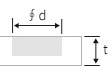
Shape
-
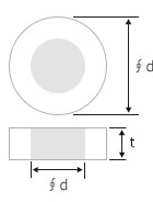
WD910~950 / 970~995
-
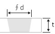
WD960 / WD970
-
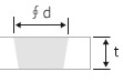
WD910 ~ 920MW
-